
Magnetization Options for Neodymium Iron Boron, Samarium Cobalt, Ceramic Magnets
At Dura Magnetics, you get the best magnet and magnetic assembly design and engineering assistance in the marketplace.
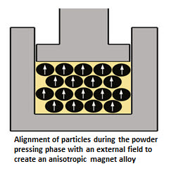
Most useful commercial magnets are anisotropic which means that they have an “Easy” or preferred direction of magnetization and that an orientation field was applied during the compaction stage of the manufacturing process. It is essentially impossible to magnetize the resulting anisotropic magnet alloy other than in the Direction of Orientation; however, various pole configurations can be achieved without conflicting with the magnet material’s orientation.
Below are conventional and standard industry options for the magnetization directions of Rare Earth Neodymium Iron Boron, Samarium Cobalt, and Ceramic magnets.

Direction of Magnetization – Orientation:
All magnetized, anisotropic magnets need to have the direction of magnetization communicated. All un-magnetized, anisotropic magnets need to have the alignment direction communicated because the magnet will be eventually magnetized and the magnets have to be made to accommodate the desired magnetization direction.
All magnetized, isotropic magnets need to have the direction of magnetization communicated, but it is not necessary for un-magnetized, isotropic magnets.
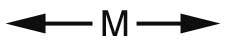
The direction of magnetization can be indicated by written communication or by drawings. Usually when written a (M) or <M> is put after the dimension which parallels the direction of magnetization.
For instance, a ½’ OD x ¾” long anisotropic Neo magnet oriented and magnetized axially would be written as such: ½”OD x ¾” long (M) or ½”OD x ¾” Long <M>. Also, for the magnet industry, it is common to leave the last dimension as the magnetization/orientation direction. This convention will work for symmetric, solid geometries, but it cannot be used for arcs, some diametric geometries, etc.
For a drawing, direction arrows can be used and labeled as the direction of magnetization identified. It is quite common to use a “M” with two arrow emanating from each side. The arrows are arranged parallel to the direction of magnetization/orientation.
Polarity Indication:
Indicating the desired magnetization direction or orientation of a magnet may not be sufficient to ensure the desired performance. The polarity of the magnet may also need to be indicated so that the magnet is integrated properly into the application and functions according to the design. This is most apparent for non-axial symmetric magnets like arcs, multi-pole rings, etc.
Sometimes the polarity may have no bearing of the magnets operation in the application, but for non-symmetric magnets, the polarity should be indicated so as to provide consistency. Magnets that do not have consistent polarities (NORTH or SOUTH) located on a particular feature may provide an extra challenge or safety issue for integrating technicians or operators.
The polarity of the magnet can be referenced on a drawing and there is no one common method. The intent is to show the direction of magnetization and any required polarity. Below are a few common techniques.


Generally magnet materials can be categorized as either Isotropic or Anisotropic. Isotropic magnets can be magnetized in any direction while anisotropic magnets have a preferred direction of magnetization. Isotropic magnets are cast or pressed without any orientation operation. This allows for a near infinite number of magnetization directions, but the resulting magnet alloy is weaker.
Isotropic magnets exhibit lower energies because the not all areas of the magnet are working in the same direction. Isotropic magnets are generally more cost effective and can be produced closer to near net shapes with less finishing requirements.
Most useful commercial magnets are anisotropic which mean they have an “Easy” or preferred direction of magnetization. The anisotropic nature is achieved by applying an orientating field during the manufacturing process. For powder metal magnets, the alignment field is applied during the powder compaction stage. Anisotropic cast magnets are oriented when an alignment field is applied during a heat-treat operation executed after casting.
It is essentially impossible to magnetize the resulting anisotropic magnet alloy other than in the direction of orientation; however, various pole configurations can be achieved without conflicting with the magnet material’s orientation.
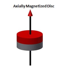
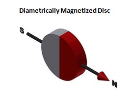
Disc magnets are most often magnetized in the axial direction, but they are also supplied magnetized diametrically, across the diameter. Both orientations are available in a variety of diameters and lengths.
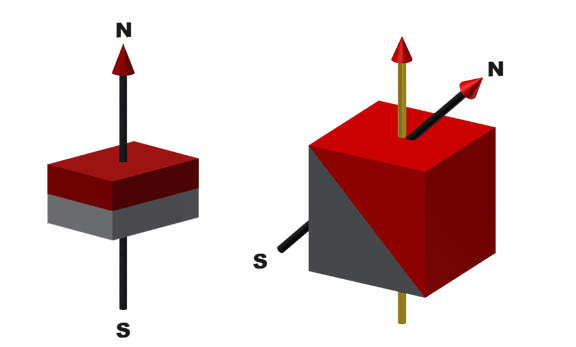
Block Geometry
Block Magnets are Rectangular or Square in shape and have three potential orientation directions. The magnets can have a near infinite number of dimensional combinations and they can be polarized in any direction.
Typically block magnets are supplied oriented / magnetized in the direction of one of the coordinate axis, but they can also be supplied with an incident angle between the orientation/magnetization direction and a geometric axis. Oftentimes this style magnet is used for arrays and most typically a Halbach array.
Ring Geometry
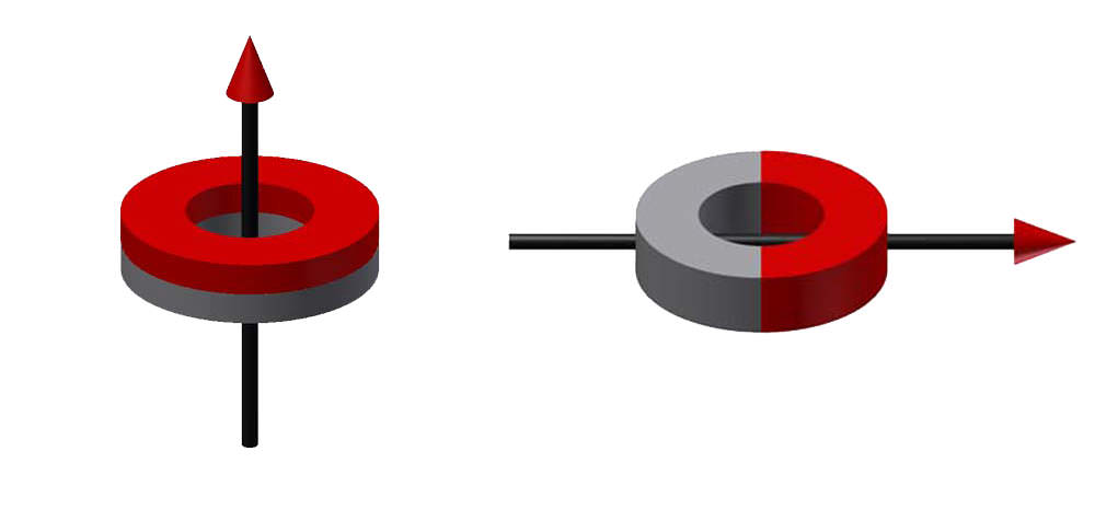
Radial Magnetization:
Radially oriented and magnetized rings are available in Neodymium Iron Boron, but there are many limitations in alloy grade, Outside Diameter/Inside Diameter ratio, axial, length, etc. Specialized tooling must be created and there is an upfront capital investment which acts as a cost inhibitor for most applications. (Radially oriented and magnetized Samarium Cobalt is not offered.)
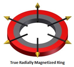
Radial Ring Magnetization Approximation:
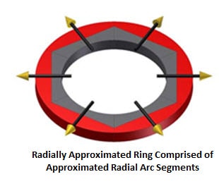
Neodymium Iron Boron, Samarium Cobalt, and Ceramic magnets can be approximated by arcs segments; however, in most cases the magnets must be assembled magnetized and there must be a large performance benefit to the application to absorb this cost. As with “True” radial rings, true radial Arc Segments are difficult to manufacture, but can be approximated themselves.
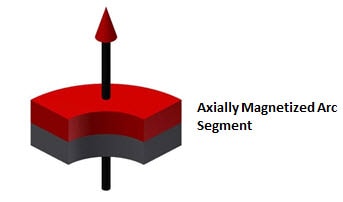
Arc Segment Geometry
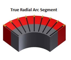
Radially IN / Radially Out:
An arc segment can be polarized NORTH or SOUTH on the Outside Radius. (The resulting opposite pole will reside on the Inside Radius.) It is very difficult to achieve a true “radial” orientation during the pressing/alignment stage of manufacturing and therefore, truly radial Neodymium Iron Boron, Samarium Cobalt, and Ceramic magnet arcs are rare and specialized. (An approximation of a true radial Orientated Radial Arc is available and widely utilized in industry.)
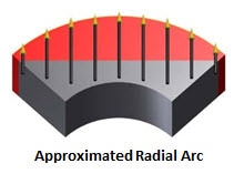
The approximated radial arc utilizes linear orientation/magnetization along a straight axis. The radial component diminishes on the leading and trailing edges of the approximated radial arc.
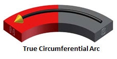
Circumferential:
Circumferential Orientation and Magnetization is not available for Arc magnets comprised of Neodymium Iron Boron and Samarium Cobalt; however, this magnetization geometry can be approximated.
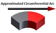
The approximated radial arc utilizes linear orientation/magnetization along a straight axis. The radial component diminishes on the leading and trailing edges of the approximated radial arc.
ITAR Registered & Compliant
We are registered and compliant with the International Traffic in Arms Regulations (ITAR). This qualifies us to work with items listed on the United States Munitions List (USML). We are also ITAR registered with the Directorate of Defense Trade Controls (DDTC).