
Magnetic Torque
Couplers / Magnetic
Linear Couplers
At Dura Magnetics, you get the best magnet and magnetic assembly design and engineering assistance in the marketplace.
Dura Magnetics designs, engineers, and manufactures magnetic torque and magnetic linear couplers for OEM power transmission applications that require a seal to prevent contamination or leakage between wet and dry systems (e.g., pumps).
Torque and Linear Couplers Overview
The magnetic field produced by permanent or electromagnets creates a condition by which a force can be exerted over a distance. This is fairly obvious to anyone who handles a magnet, when the magnetic field produced by a magnet has an affect on a ferrous object at a distance. Meaning, that a magnet need not touch an object in order to exert a force on it. The ability to exert a force through a “gap” will also facilitate propagation of the object. This is most notable in a torque coupler where two magnetic assemblies operate through a gap and torque can be transferred from one assembly to the other without direct mechanical contact. A linear version of this “coupling” effect is also fairly common and instead of a rotational force, a linear “coupling” force is transferred between the two magnet assemblies.
This magnetic coupling, both rotational and linear, is helpful when one needs to separate operational environments. For instance, a rotational coupler can be used to drive an impeller inside a pressure vessel. The external motor is attached to one side of the torque coupler half and the impeller, inside the pressure vessel, it is attached to the second coupler half. The impeller is successfully “driven” by the motor even though there is no mechanical contact.
Linear couplers are often employed when pressurized air is used as the driving force. For instance, a linear couple affixed to a piston located inside of a tube will transfer a linear force to an outside carriage affixed to the external coupler assembly as pressurized air drives the piston.
Typically, the cost of a torque or linear coupler exceeds the cost of common mechanical solutions, but couplers are employed when mechanical linkages are not feasible.
One of the largest expenses of a coupler is the magnet component. For custom coupling devices, the magnet alloy must be minimized to yield a viable commercial design. The operating environment also adds cost and complexity. One half of the coupler is usually operating in an aggressive environment that may include:
- High pressure
- Temperature Extremes
- Caustic liquids or gasses
- High degree of particulates or fouling agents
Performance Detractors:
- Gap: As the distance between the operating halves of the coupler increases, the torque or force transfer decreases. The unit should be designed to minimize the operational gap between the coupler halves. (Non-symmetric gaps can create undesirable vibration.)
- Angular Misalignment: The geometric axes of both halves should be co-axial or the performance will degrade and unwanted vibrations can be created. (Torque)
- Heat: Typically, as magnet alloy is heated the resulting field density decreases. This drop in density reduces the effective torque/force transfer between halves.
Magnetic Torque Couplers
The “synchronous” style of torque coupler is the most common. There are two primary version of the synchronous style – “Face to Face” and “Coaxial.”
Face to Face:
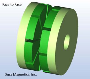
This style is comprised of disc shaped assemblies. The discs have a single active magnet surface/side which must be “facing” in order to couple. The discs are usually comprised of several magnets affixed to a mild steel backing-plate or housing. The severity of the operating environment will dictate the housing material for the magnet.
The Face to Face coupler’s torque transfer capability increases as the Outside Diameter (OD) increases. This is because the effective magnet material acting to “couple” increases as well as the resulting “lever-arm.” This can be a disadvantage because the coupler may need to have a large OD to couple the target torque. A large OD may negatively impact the ability to integrate the coupler because of size. It also limits the rotational speed.
Face to Face couplers are a good low cost solution when the required torque, speed, and size restraints are moderate.
Coaxial:
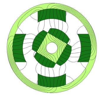
This style is comprised of an Inner Assembly (Half) and an Outer Assembly (Half). The active surfaces for this coupler type are on the Outside Diameter for the Inner Half and on the Inner Diameter for the Outer Half.
Unlike the Face to Face coupler, the Coaxial Coupler’s torque transfer ability will increase as the axial length in increased as well as when the diameter of the halves is increased. Increasing the axial length is the most common method of gaining torque transfer ability with a coaxial coupler. Increasing the axial length is also the most cost effective method when compared to increasing the Outside Diameter.
Coaxial couplers are usually of higher cost than Face to Face couplers, but they usually offer a space savings.
Magnetic Linear Couplers
Similar to a torque couple, a Linear Coupler relies on magnetic interaction between two coupler halves. As in the torque coupler, usually one Half is the driver and the other Half is the follower. Linear couplers are often simpler to design and to construct when compared to torque couplers because the movement is linear and non-rotational.
A linear coupler can be as simple as two magnets or comprised of engineered arrays containing multiple magnets of various configurations. The operational gap between the coupler’s halves, the required coupling force, and the operating environment are the prime design variables.
There are many variations of Linear Couplers and the fundamental similarity is that the coupler’s “Halves” are “linked” through a gap. One “Half” can propagate the other “Half” without contact. All of the common and unique designs for Linear Couplers try to minimize cost, increase performance, and make use of the application specific geometry.
One common style of Linear Couplers are simple magnets on a backing-plate. The magnets are sized based on the gap and desired force to be transferred. (As previously discussed the larger the gap, the less magnetic flux linking will occur and this results in a lower coupler force.) The simplest design is two magnets alternating NORTH – SOUTH. The backing-plate connects the non-working faces of the magnet and increased the effective filed in the gap and therefore the coupling force.
The magnet’s cross-sectional area, the magnetic length, the spacing between the magnets, the backing-plate alloy, and the backing-plate thickness are all variables in the design and need to be optimized for the needs of the particular application.
The two magnets per “Coupler Half” system can be expanded to three or more magnets per half to add additional coupling force. The constraint is the available “room” and cost.
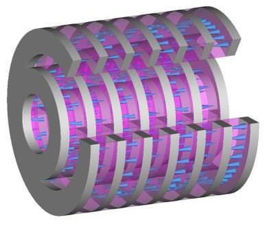
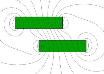
The second most common Linear Coupler style uses “Steel Poles” as the working areas and is used extensively in “Round” applications, especially when pipes are employed.
Ideally “radially” orientated magnets would be used for this geometry, but this orientation is very challenging to produce, is very expensive, and has limits on the OR and IR of the magnets.
More Information: Magnet Magnetization Geometry Page
To circumvent this limitation, axially orientated magnets are used in conjunction with steel poles, and this facilitates 360° coupling. The magnets are “sandwiched” by the steel poles and the magnet-steel pole pattern alternates to the required axial length. (The axial length of the coupler halves is the primary driver for the coupling force.)
Similar to a Torque coupler, this style of Linear Coupler has Inner and Outer array halves; however, there is no rotational coupling capacity.
Theory of Operation
In the simplest form, magnets are able to exert a force over a distance. Whether by inducing a field in a ferromagnetic material or interacting with another magnet, a magnet can exert a force without touching. The magnet’s magnetic field is the mechanism for this non-contact force.
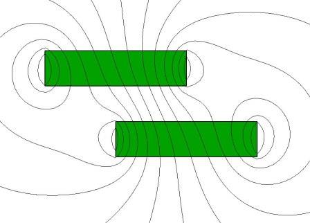
When two magnets are attracting through a gap, are restrained from engaging, and are otherwise at equilibrium, then no force components are created other than those trying to bring the magnet together. If one of the magnets is shifted, then the magnetic field “bends” and “sideways” force components are established to maintain the equilibrium. (This force acts to oppose the motion of the shifted magnet and to propagate the second magnet so that the system can remain in or achieve equilibrium again.)
Additionally, there were “sideways” magnetic field components and there-by sideways force components before the shift, but there were equal number and hence the system was at equilibrium. When one magnet was shifted the symmetry of the field was skewed and the sideways field components became unbalanced resulting in a net force to drive the system back to equilibrium.
These sideways force components are the mechanism which allows for Linear and Torque Couplers. While more prevalent, Torque Couplers are really Linear Couplers, but with rotational motion. The “Linear Force” is the force acting tangential to the radius of the system. The summation of the effective tangential acting forces for all magnet elements in the system multiplied by the radius of the system results in the effective torque.
(F1 + F2 +… Fn) x Radius = Effective Torque
(Where F is the force acting tangentially to the radius for each array element up to “n” elements.)
As described above, Force components are established by skewing the symmetry of the system. These force components are established by the bending of the magnetic field lines. The relative intensity of the force corresponds to the degree of flux line bending. The range is effectively zero for a system at equilibrium to some maximum which is depends upon the system’s geometry and the coupler design.
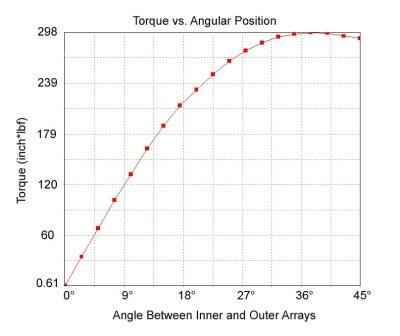
Since there is a range, this would assert that there must be some relative motion before a linear force or torque is created. This motion is what we call the “pitch” and it may need to be accounted for during the design. For instance, for a particular Torque Coupler, the maximum torque may not be achieved until the system has rotated through 15°. This may or may not be an issue for some applications, but it must be observed that maximum Torque and maximum Linear Force occur at the maximum system skew.
If the system is driven past this maximum skew, the Torque and Linear Coupler Halves will “slip” and essentially decouple. The halves will not couple until all motion has ceased. (Typically Linear Couplers must be reset and forced back into the desired position. Linear Couplers, once decoupled, will oppose being coupled again.)
Design Considerations
- What is the operational environment? Having a proper understanding of where the magnet or magnetic assembly is used helps to clarify materials selections.
- What is the target gap? Can the target gap be minimized since this parameter is a first order cost driver?
- What are annual usage requirements? Low volume applications requiring high coupling torque values require complex magnet arrays which drive higher costs.
- What is the Rotational/Linear speed?
- What are the required mechanical features? Will your coupling application require mounting holes, shoulders, etc.? What is the shaft size?
ITAR Registered & Compliant
We are registered and compliant with the International Traffic in Arms Regulations (ITAR). This qualifies us to work with items listed on the United States Munitions List (USML). We are also ITAR registered with the Directorate of Defense Trade Controls (DDTC).