There is a time and place to use Halbach Arrays over conventional arrays. Depending on your needs, the time and cost involved in manufacturing Halbach Arrays may or may not be worth the investment. This final piece in our four part series on Halbach Arrays discusses the benefits and drawbacks to using these arrays.
Magnetic Circuit Design Comparison (When to Use a Halbach Array)
Despite the many beneficial properties of a Halbach Array, it is not necessary to use a Halbach Array for every application where magnetic fields are needed. It has been pointed out that the Halbach Array is a more efficient use of magnet alloy, but is that enough to employ it in a design? This is an especially pointed question with the increased difficulty in manufacturing.
How Do Operational Gaps Affect Attractive Force?
| Three Magnet Geometries Inspected Through Three Different Operational Gaps |
| Attractive Force (lbf.) |
Gap (Inch)
| All NORTH
| Alternating N-S-N-S-N
| Halbach Array
|
| 0.000" | 80 | 105 | 112 |
| 0.010" | 70 | 91 | 102 |
| 0.060" | 36 | 36 | 57 |
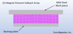
The accompanying table is a compilation of three magnet geometries inspected through three different operational gaps: direct contact, 0.010”, and 0.060”. The magnet geometries all used the same amount of magnet material, (5) 1/2” cubes, and had the same working surface. Also, the geometries had a thin backing-plate which helped the efficiency of every case.
The results show that the Halbach Array configuration was the best performer, but the disparity in performance between the different magnet geometries was not that great.
The Halbach geometry had the best performance when a gap was involved. This makes sense, as the magnetic circuit is more efficient than the others, but a simple alternating pole geometry yielded similar performance at or near direct contact with the workpiece. This data suggests that Halbach designs would work best when a “gap” exists in the application. Without a gap, a conventional alternating pole or standard magnet assembly using a steel return path should be employed.
Negative Aspects of Halbach Arrays
The main disadvantage of the Halbach Array geometry is that it is difficult to assemble. All of the magnetic elements repel each other in a Halbach Array, which can create a variety of assembly issues:
- Needing to assemble the magnets magnetized
- Combating the forces during assembly
- Ensuring the assembly will “hold together” during its use
The benefit is increased performance, but this benefit comes at a cost of increased difficulty in manufacturing.
Another disadvantage is that the magnets are arranged in a direct or quasi-direct repelling condition. This means that magnets in the same array are acting to demagnetize their neighboring magnets. With a high coercivity alloy, this may not be an issue, unless elevated temperatures are required in the application – as the operating temperature increases, a magnet is more susceptible to demagnetizing, and the neighboring magnet demagnetization is exacerbated.
Benefits of Using a Halbach Array
The most obvious benefit of a Halbach-style Array is that the field produced is very strong when compared to other arrays having the same amount of the magnet alloy. The arrangement essentially increases the efficiency of the magnetic circuit.
The by-product of the design is that there is only one working surface or “working face.” The one working-face, where the magnetic field resides, is very strong; and the non-working face has essentially no field. In essence, the magnetic field, which would normally be present on the non-working face, is rerouted to the working-face. This is true for both Circular and Planar style Arrays.
Summary of Halbach Arrays Performance
We hope that these last few posts has enhanced your understanding of Halbach Arrays, how they work, and when they should be implemented. As we wrap up this four part series on Halbach Arrays, remember these four key points:
- Halbach Arrays or magnet geometries utilizing a “Bucking-Magnet” can improve the efficiency of the magnetic circuit.
- Halbach Arrays can be circular or Planar, and they have one predominant side/surface where a majority of the magnetic field resides.
- Halbach Arrays may have an issue in high heat applications, because the array elements apply a demagnetizing field on each other.
- Halbach Arrays work better than conventional arrays when a “gap” is present in the application.
There are many opportunities for a Halbach design to improve performance. Consult Dura Magnetics for application assistance with your array design to see if a Halbach Array can enhance your magnetic applications.