Function and application influence design choices. The balance between power and cost efficiency, for example, is a tough line to walk. So for many, the basic design elements of the Halbach Arrays and its analogues are of vital consideration. In this third article of our four-part series on Halbach Arrays, we will discuss design elements and variables.
Analogous Array Designs
The term Halbach Array is ubiquitous. It’s liberally applied in a generic sense when an array has an arrangement of magnets where the orientation has a rotational iteration. Most Planar Magnet Arrays, which use this technique, incorporate a 90° orientation directional change from magnet element to magnet element. It is common to introducing magnets with orientations other than the pole facing the work-piece (in this case horizontal). These horizontally orientated magnets are referred to as “Bucking Magnets.”
So, when an array design makes use of “Bucking Magnets”, the array may or may not be a Classical Halbach Array; however, most will still refer to the array as a Halbach Array.
Bucking Magnet Arrays
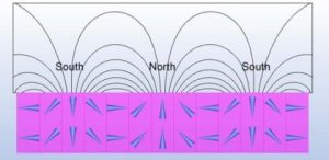
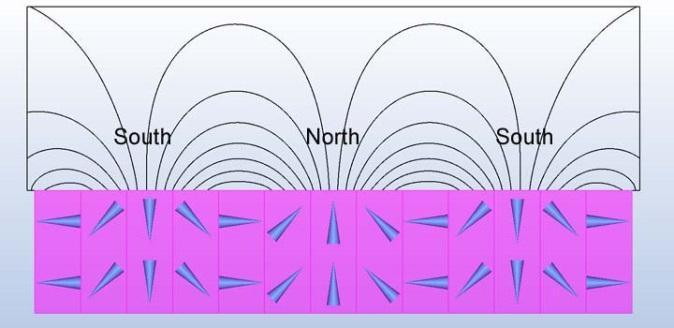
A Halbach Array utilizing 45° angles between the magnets.
There are several styles of Halbach Arrays or arrays which make use of “Bucking Magnets” The most accessible online depictions show arrays using a 90° orientation change between magnet elements, but there are many more available.
A 90° difference between array elements is somewhat “coarse”, and using more array elements with small angles will more closely approximate a true circumferential orientation.
The figure to the right uses 45° angles between the magnets. This is closer to circumferential orientation and improves the efficiency of the system.
Bucking Magnet Utility
It is unknown whether or not the extra effort in using the finer resolution is beneficial.
Typically, the higher the number of elements utilized, the finer the angular resolution, resulting in a more homogenous and stronger the field output will be.
However, there is a point of diminishing returns where the manufacturing difficulties outweigh the magnetic field benefit.
As with most magnetic circuits, a designer balances the need of the application with cost. A Halbach Array adds cost, but it also can reduce the required magnet mass while increasing performance.
Design variables include
- Operational gap:
- the gap between the work-piece and magnet array for a Planar design
- the required gap in the ID of a Halbach Cylinder
- the gap between a Halbach Rotor and the stator
- Operational environment (temperature, rotational speeds, liquids, gasses, etc.)
- External demagnetizing fields (especially on rotors)
- Required lifetime in service
- Cost
- Available room or volume allotted to the array.
We know that design, utility, and external variables are inextricably connected in many applications. Halbach Arrays are no different. In our upcoming final piece of this four-part series on Halbach Arrays, we will discuss when it’s most prudent to use a Halbach Array, including some key benefits and drawbacks to its use and implementation.
